For our final project, we propose a cube with which you can play various games with (a game cube if you will) that will at the same time be very esthetically pleasing. To accomplish this we will encase our arduino inside of the cube (making sure that it is stable) and run an RGB LED to each face of the cube. The cube will be controlled by an accelerometer which will inturn control the color values for each RGB LEDs.
We are still brainstorming some of the games and/or settings that will be available for the cube but so far we have:
Color Wheel - a setting that will allow you to create every color in the color wheel simply by rotating and moving the cube along the x, y, and z axis'.
Maze Game - a game in which you have to figure out the right combination of turns for the cube in order to reach the end of the "maze".
Simon^{3} - similar to simon but utilizing rotations to certain sides of the cube instead of pressing buttons (sound may be incorporated). Each side of the cube will also have it's own color. These six colors will be red, yellow, green, cyan, blue and magenta being that yellow, cyan, and magenta are all composed of equal values of two of the three primary colors (red, green, and blue).
Reflex Game - a game in which you must rotate the cube to the indicated side before time runs out, while your granted time limit between each rotation gets smaller and smaller as the game progresses.
Color Game - at the start of the game the cube will flash a random color and it will be your job to create an identical color to the one that was shown at the start of the game, which will inturn have some sort of response if you create the correct color.
In these labs we learned how transistors can be used to allow you to control a circuit that is carrying a higher current and voltage from the microcontroller and how an H-bridge can be used to switch the direction of a current that is flowing through a circuit. An H-bridge is actually made up of several transistors aswell. Here is a video demonstrating how the H-bridge allows for a change in dirrection of current as well as how the H-bridge acts as a transistor by allowing control of the circuit while it is carrying higher current and voltage from our power source.
We did have one minor issue while attempting to complete this lab. On our first trial nothing would work. At that point I decided I'd feel what I thought to be the H-bridge to make sure it was not heating up. After almost burning my finger off I realized something must be wrong. We checked the diagram, made sure everything was in the right place, switched wires away but nothing seemed to work. At that point we realized that what we thought was a H-bridge was actually a shift register. After a quick switch we had our circuit running.
In this lab we learned how shift registers work and how they can be used to control eight outputs at a time while taking up only a few pins on your micro controller. This is done using a thing called "synchronous serial communication" which allows you to pulse one pin up and then down allowing you to communicate a data byte to the register bit by bit. Once the whole byte is transmitted the HIGH, LOW messages located in each bit are then transmitted to its corresponding output pin. Here is a diagram of the shift register we used for the lab:
PINS 1-7, 15
Q0 " Q7
Output Pins
PIN 8
GND
Ground, Vss
PIN 9
Q7"
Serial Out
PIN 10
MR
Master Reclear, active low
PIN 11
SH_CP
Shift register clock pin
PIN 12
ST_CP
Storage register clock pin (latch pin)
PIN 13
OE
Output enable, active low
PIN 14
DS
Serial data input
PIN 16
Vcc
Positive supply voltage
Our overall goal for this lab was to control a seven segment LED counter using . We had a few problems while trying to figure out what pins controlled what on the counter but after we discovered that it was a common anode counter it was smooth from then on. We were able to control the counter by using only 3 pins in our arduino.
For this project we were asked to design and prototype an object for the kitchen area so naturally we came up with the idea of a 'virtual' fruit slicer that we like to refer to as ninji chop. My partner and I had done some experimenting with an accelerometer after lab one day and we thought it was pretty cool so we decided that we wanted to implement this into our project in some shape or form. All of our first ideas incorporated the accelerometer in such a way as to cause some type of pouring action for perhaps a pitcher or a measuring cup. This idea flopped after we realized that liquids handled in the kitched are generally too heavy for the type of devices we have access to in the lab and it just didn't seem very innovative. After wrestling around with several other ideas that were simply preposterous we came up with the accelerometer controlled knife.
Here is a video of our first test to see if a servo could exert enough force to cut a banana.
Check.
After some brain storming we realized that our design process would circulate around the knife being controlled by our acceleromter, so clearly the next step was to get the thing chopping! After mapping the values of the y-axis inputed from our accelerometer to the values outputed by the servo connected to the knife we came up with the following.
Notice the "glove of power".
The idea of a 'virtual' fruit chopper in which every physical action exerted by the device could be controlled from a glove raised one design question after another when we realized that there were more factors at play here other than a simple chopping motion. We of course wanted to make it as interactive as possible. As you can see in this next video we mounted our knife/servo to our main platform in order to keep it stable, as to apply the maximum amount of force on the food item being sliced, but we needed a way to pull the food along to create uniform cuts.
You would not believe the number of systems we thought of to pull our little cutting board along. From linear actuators to complex systems of gears we knew there had to be a perfect design out there that could fulfill our needs. We finally realized the elegance of simplicity when we setteled on a dual spindle/pulley system that would give the operator ultimate control over the cutting board, anywhere from thinly sliced to chunky. In order to mount the servos that would control the spindels we had to raise the main platform that the cutting board would slide on. This was done using blocks of wood. The peice of wood you can see mounted to the knife servo was placed there for added support.
We then mounted two buttons to our "glove of power" in order to control what directions the the spindels would pull. We had to run through trial and error in order to figure out what values would cause the servos to spin in certain directions at certain speeds. We then fixed a block of wood with a hole drilled through the middle to each end of the cutting board. Next we hot glued some string from each spindle to it's corresponding block. Here is a video of the first demonstration of one of our spindels in action.
We then had to coordinate each spindel such that they would spin in the same direction when a button was pressed (depending on which button was pressed) such that one would pull the cutting board along while the other would release it's line. We ran into a minor problem in our code while sorting this out when we could only get it to pull one way. We actually created an if statement for each button when instead we simply needed to apply both buttons to one if statement. In doing so our program no longer skipped checking to see if the second button was pressed. Our cutting board also ended up in several "truck pulls" before we got the rotations figured out as well.
Another element we needed to think of was a way to keep the slices of fruit from falling off of the cutting board. This problem was solved by fixing two "walls" on both sides of the path that the cutting board would take, helping to contain the fruit and to funnel the cutting board at the same time.
Next we needed a way to stop our spindels if they were to reach the end of the platform. This was done by placing a switch at both ends of the platform. When one switch is pressed our program skips the part of the if statement that checks to see if the button that would pull the cutting board toward the currently pressed switch and simply checks to see if the other button is pressed, and this will of course loop until the other button is pressed.
After we got both servos that control the spindels functioning we experienced a problem with our servo controlling our knife, that being it became nonresponsive. After some research we discovered that the arduino power source is simply not enough when it comes to powering multiple servos. We then found an external power source as you can see below.
We did however experience the persisting problem of our knife randomly locking up, usually happening whenever you hold the glove (with the accelerometer attatched of course) still for a few moments. The knife would become responsive again from a simple tap but it is simply annoying. If you have any comments on the matter feel free to indulge us on what it is that you think the problem may be.
Last but not least here is a video of our final project. Our final design implemented a blade gaurd as to stop any slices of fruit from getting stuck to the blade. We think it turned out pretty well.
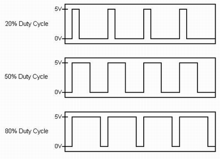
In this lab we learned how to utilize Pulse Width Modulation or PWM even more in order to demonstrate analog output. PWM can allow digital devices to produce analog output by simply turning the digital device on and off very quickly. The pulses of "on" time that are part of each period of PWM are referred to as duty cycles.
During the first part of lab we constructed the following circuit in which to control a motor from a potentiometer. We wrote a program in which we could manipulate the duty cycle of the motor by twisting the potentiometer. We also incorporated an LED in which is manipulated in the same manner as the motor.
Next we uploaded some started code provided to us in order to become more familiar with servos.
This one being a 360 degree servo:
And this one being a 180 degree servo:
Next we added a potentiometer to our circuit and mapped the analog input values of the potentiometer to the analog output values of the 180 degree servo.
In the final portion of lab we got to play with a small piezo speaker.
My partner being gifted in the art of music making looked up the frequencies for certain notes online in order to demonstrate another melody.
In this lab we performed a number of experiments using our Arduino and analog input. Analog input values differ from digital input values in the sense that analog values can be numbers other than 0 and 1. The Arduino has 6 pins that can be used for analog input. These inputs take a voltage of 0 to 5 volts and converts it to a value between 0 and 1023. These converted values can then be used as variables within a program which creates an almost limitless number of possibilities that they can be applied to. We got to play with devices that can be used to input these values into our Arduino. The first device we got to use was a potentiometer which changes the amount of resistance on the voltage value that it outputs by twisting it left or right. After setting up the following circuit we used code provided to us during the lab to implement the following:
As you could see in the previous video our code implemented pulse width modulation (PWM) by using the analog values inputed by the the potentiometer to determine the delay between when the light turned on and off. Here's an example of how pulse width modulation looks on paper, the duty cycle referred to describes a portion of "on" time as opposed to the period which consists of one whole interval of both on and off time:
As you can see in this next video, the pulse width modulation is no longer noticeable in the sense that you can't physically see the LED turning on and off. It simply appears to be dimming but it is in fact implimenting the use of PWM by making the interval between "on" and "off" small enough to where your eye can no longer see the individual on/off stages.
In the next part of lab we began a series of experiments having to do with environmentally controlled analog input devices, the first of which being a photo resistor. Using the code provided we constructed the following using the same circuit from the potentiometer experiment, but with a photo resistor instead of a potentiometer of course:
As you can see in the video above, the photo resistor inputs votage to the Arduino depending on the amount of light it registers. After completing this circuit we decided we'd make a "night-light". We modified our code so that once the sensor reached a certain value the LED would remain on as long as the sensor value remained equal to or greater than that certain value as you can see in this video.
Our next task was to set up a temperature sensor. Using some code that was provided to us and some pretty complicated math in order to convert the input values from the sensor into values of Fahrenheit we demonstrated our temperature sensor by inserting it into a cup of hot water. The Arduino serial monitor displays the temperature values in real time.
Next we went about setting up a pressure sensor that would light up an LED depending on the amount of pressure applied to the sensor. This is the same concept as the previous experiments but simply using the amount of force applied the sensor to determine the amount of resistance applied to the amount of voltage the sensor outputs, thus creating different analog values that the Arduino can read.
Next we set up a circuit that incorporated a flex sensor. The only difference between this an the pressure sensor was that it inputs values depending on the amount of flex on the device.
Problematic Occurences
We did run into a few problems with our temperature sensor set up. The wires were not color coded and we thought we had a working circuit for a minute but our sensor started to heat up rapidly and we realized we had wired something wrong. We quickly fixed this problem. All in all this was our least problematic lab yet!
After Lab Fun
After the lab was finished we decided we'd play around another analog input device called an accelerometer. An accelerometer inputs three different values depending on what direction it is facing on the x-axis, y-axis, and z-axis, with the z-axis pointing straight up and down. We decided to map the values being inputed from the y-axis to the intensity values of an LED. It worked brilliantly. Click on the link below to see the video of our accelerometer/LED and tell us what you think.
I did end up thinking of another possible idea for another day in the lab. I was thinking of perhaps mapping the 3 analog values inputed from the an accelerometer to the values of a RGBLED (red, green, blue). In theory by doing so you should be able to get the RGB to produce every possible color combination there is by simply rotating and moving the accelerometer along the three axis'. Just some food for thought.