Wednesday, October 3, 2012

Analog Input Lab

In this lab we performed a number of experiments using our Arduino and analog input.  Analog input values differ from digital input values in the sense that analog values can be numbers other than 0 and 1.  The Arduino has 6 pins that can be used for analog input. These inputs take a voltage of 0 to 5 volts and converts it to a value between 0 and 1023.  These converted values can then be used as variables within a program which creates an almost limitless number of possibilities that they can be applied to. We got to play with devices that can be used to input these values into our Arduino.  The first device we got to use was a potentiometer which changes the amount of resistance on the voltage value that it outputs by twisting it left or right.  After setting up the following circuit we used code provided to us during the lab to implement the following: 
 
 
As you could see in the previous video our code implemented pulse width modulation (PWM) by using the analog values inputed by the the potentiometer to determine the delay between when the light turned on and off.  Here's an example of how pulse width modulation looks on paper, the duty cycle referred to describes a portion of "on" time as opposed to the period which consists of one whole interval of both on and off time:
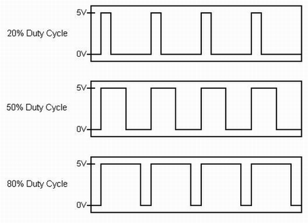


As you can see in this next video, the pulse width modulation is no longer noticeable in the sense that you can't physically see the LED turning on and off.  It simply appears to be dimming but it is in fact implimenting the use of PWM by making the interval between "on" and "off" small enough to where your eye can no longer see the individual on/off stages.


In the next part of lab we began a series of experiments having to do with environmentally controlled analog input devices, the first of which being a photo resistor.  Using the code provided we constructed the following using the same circuit from the potentiometer experiment, but with a photo resistor instead of a potentiometer of course:
 
 
As you can see in the video above, the photo resistor inputs votage to the Arduino depending on the amount of light it registers.  After completing this circuit we decided we'd make a "night-light".  We modified our code so that once the sensor reached a certain value the LED would remain on as long as the sensor value remained equal to or greater than that certain value as you can see in this video.
 
 
Our next task was to set up a temperature sensor.  Using some code that was provided to us and some pretty complicated math in order to convert the input values from the sensor into values of Fahrenheit we demonstrated our temperature sensor by inserting it into a cup of hot water.  The Arduino serial monitor displays the temperature values in real time.
 
 
Next we went about setting up a pressure sensor that would light up an LED depending on the amount of pressure applied to the sensor.  This is the same concept as the previous experiments but simply using the amount of force applied the sensor to determine the amount of resistance applied to the amount of voltage the sensor outputs, thus creating different analog values that the Arduino can read.


Next we set up a circuit that incorporated a flex sensor.  The only difference between this an the pressure sensor was that it inputs values depending on the amount of flex on the device.

 
Problematic Occurences
We did run into a few problems with our temperature sensor set up.  The wires were not color coded and we thought we had a working circuit for a minute but our sensor started to heat up rapidly and we realized we had wired something wrong.  We quickly fixed this problem. All in all this was our least problematic lab yet!

 
After Lab Fun
 
 After the lab was finished we decided we'd play around another analog input device called an accelerometer.  An accelerometer inputs three different values depending on what direction it is facing on the x-axis, y-axis, and z-axis, with the z-axis pointing straight up and down.  We decided to map the values being inputed from the y-axis to the intensity values of an LED.  It worked brilliantly.  Click on the link below to see the video of our accelerometer/LED and tell us what you think.


I did end up thinking of another possible idea for another day in the lab.  I was thinking of perhaps mapping the 3 analog values inputed from the an accelerometer to the values of a RGBLED (red, green, blue).  In theory by doing so you should be able to get the RGB to produce every possible color combination there is by simply rotating and moving the accelerometer along the three axis'. Just some food for thought.


Tuesday, September 18, 2012

Freekout! The game that's sweeping the nation!

 
For this project we were asked to design and implement something that demonstrates both digital input and output to realize some kind of creative physical interaction.  In this case our input was our two buttons.  This game is like a version of pong with a twist to it.  The lights will start by turning on and off, appearing to give either a clockwise or counterclockwise motion.  The first person the light reaches has to press their button during the time that the LED, located in front of their button, is lit.  In doing so the light will reverse it's motion and reverse toward the other player.  Although if you were to miss time your button press the light would not reverse in direction and you would know that you mistimed your button press.  Every time there is a successful "bounce-back" the incrament of time between each light turning on and off gets smaller, giving the appearance of a faster moving light.  After a player misses 5 times the other player is deemed the victor and the LED's on his side of the game board light up. 

Here's a few pictures of the initial process of the initial process of handywork/presoldering to give us a better idea of how our game was going to funcion.


After attempting to get the thing wired to the breadboard we did run into to  the little problem of not know which side of the pins that we soldered from our wires to our LEDs was positive and which side was ground.  This was solved by plugging the pins directly into our arduino to figure out which pin was which.  In doing so we marked every wire running to ground on the LED with a sharpie.  The image on the right is the product of a piece of code that lets you know who the official victor was.
 
 
Here's the beginnings of our foamcore frame that will encase the innerworkings of our game (breadboard, wires, and arduino).
 

Here's a video of us running a loop in our program after we discovered how to get each light to blink in concession clockwise.


The video below is of the final product of our programming.  It still had a few minor flaws at this point and we were going to make it even more aesthetically pleasing and exciting but after this video was taken we accidentally shutdown the desktop computer we were working on and deleted all of our code.  We did try to rewrite rewrite the program from the original code, but we thought it would be best not to try and upload it seeing as how our game functioned well enough for presentation with the original program still uploaded to it.
 
 
This is a video of the final product, frame and all.  We found that Freekout was a proper name for the game because it always seems to start off rather slowly but gains alot of momentum towards the end of the game causing you to "freekout" at the very end.
 

"Psycopathology of Everyday Things"

  • Well designed fabricated objects should be easy to interpret and easy to use and it is suprising how many items there are out there today that have neither of these aspects.
  • The correct parts must be visible and they must convey the correct message.
  • The fact that I did not realize that I could switch to the next page using the right arrow key, because the down arrow key would not do so, until just now. (just throwing that out there)
  • If people keep buying poorly designed products, manufacturers and designers will think they are doing the right thing.
  • A good conceptual model allows us to predict the effects of our actions.
  • When the number of possible action exceeds the number of controls, there is apt to be difficulty.
  • Mappings follow from the principles of perception and allow for the natural grouping or patterning of controls and feedback.
  • Feedback is a well known concept in the science of control and information theory.

Monday, September 17, 2012

Digital (i/o) lab

This week we got to play with our breadboards a little more, aswell as take a look at some basic sample code to help us get a better understanding of input, output, and the inner workings of our arduino.  Our first step was wire up a simple LED and to upload our sample code to our arduino to get a better physical understanding of how the code loops through, making our LED blink on and off every second.  Our next step was to properly wire in seven more LED's, using seperate pins from our arduino for each LED as to control each LED in a certain way, as you can see from the video below.  I thought it was very interesting how the code was set up to run certain loops for only certain amounts of time using for(int i=0, i < 8; i++) which would cause the loop to repeat eight times.

 
Our next step was to set up a small motor we were provided with.  This required the use of a transistor in order to provide enough current for our motor.  We did experience several problems when trying to provide power for our motor. We added a small breadboard on the right hand side of our original breadboard on the first day of lab and it turns out that not all of the vertical sections of the added breadboard are connected to one another.  We simply had to make sure that our pins were all plugged into the same section of the breadboard.
 
 
The next part of our lab was to wire up another LED, but one that could be turned on and off via pushbutton.  This section of lab allowed us to focus more on how inputs worked instead of just outputs.  We learned more about how the arduino detects for the voltage of a pin to sense whether  a button is pressed or not.  For example, in this picture the arduino detects the pin to be LOW.


And in this picture it is detected to be HIGH.


Tuesday, September 11, 2012

Imaginary-Expressive-Object


This week we were asked to come up with an imaginary expressive object so I came up with:
 
THE FEEDBACK DISC
Enhance your game so you can start rattling those chains.
 
It is an electronic disc golf disc that will give you feed back in all of the key areas that can be improved to enhance your disc golf game to the fullest.  The Feedback Disc comes complete with four screens, equally seperated as to not upset the balance of the disc, that give you instant feedback in four key areas; Rotations Per Minute, launch angle, distance traveled, and hangtime.  The feedback disc employs four sensors/buttons that test to see whether the disc is in contact with your hand or not.  After pressing and holding a button for a few seconds it senses that your are ready to throw and once the disc is released from your hand it begins compiling data on it's flight until it detects any type of contact (hopefully not the tree right next to you).  It also uses a tiny accelerometer to test for the initial launch angle.
 After a tough day out on the course take your disc home and plug it into your computer, via usb, for even more FEEDBACK!  The disc comes complete with a program that can produce a 3D rendering of each and every drive you through from the day as well as a rendering of all of your drives averaged together.  The ultimate tool in knowing exactly how your disc will fly in the future.

Monday, September 10, 2012

Lab 2: Basic Electronics

 
In lab 2 we got to become a little more familiar with breadboards, multimeters, and other various components associated with breadboards. The first step of the lab was to simply make sure that our wonderful instructors set us up with all of the parts we needed for the lab. The next step was to make sure that our multimeter was working properly by touching the two probes together to test for continuity.
 
 
We decided to try out the arduino 5V power supply this time instead of the power jack we constructed in the last lab just so we could become more familiar with how the arduino worked (because we're guessing we might end up using it later on).  We used our multimeter to test various things including the small switch that we were provided.  We also used our multimeter on different resistors that we were provided.  We learned how to set up the multimeter when trying to detect for a particular resistance (in ohms) by setting it to the same range of resistance we wanted but slightly higher.  We then installed a 5V voltage regulator to keep the voltage constant.
 

Next we installed an LED and the switch.  This was our first trial in which we discovered that our button was not installed correctly as you can see the light is on when the button is not pressed and it turned off once the button was pressed.  This could have been fixed by rotating our switch either clockwise or counter-clockwise.

 
Lastly we changed out the button switch for the potentiometer you see below.  Using three alligator clips we were able to connect the potentiometer to some pins eliminating the need for solder.  The only issue we had was that turning the potentiometer only half of a rotation cut the LED completely off.


Tuesday, September 4, 2012

Sensor-Walk


 Both of these sensors detect movement, the black one controls the lock on the door while the white one controls the lights, turning them on if it detects movement or turning them off if it doesn't detect movement for an extended period of time.

This sensor is a little different. It has an on/off switch that is easily accessible to anyone in the room but if it is turned on and it goes a certain period of time without sensing any movement in the room it will conserve energy and shut the lights off anyway.


This thing is pretty nifty.  The sensor detects if there is anything under the water dispensor and if so it turns the water on allowing to fill your bottle.