In this lab we performed a number of experiments using our Arduino and analog input. Analog input values differ from digital input values in the sense that analog values can be numbers other than 0 and 1. The Arduino has 6 pins that can be used for analog input. These inputs take a voltage of 0 to 5 volts and converts it to a value between 0 and 1023. These converted values can then be used as variables within a program which creates an almost limitless number of possibilities that they can be applied to. We got to play with devices that can be used to input these values into our Arduino. The first device we got to use was a potentiometer which changes the amount of resistance on the voltage value that it outputs by twisting it left or right. After setting up the following circuit we used code provided to us during the lab to implement the following:
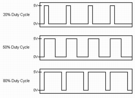
As you could see in the previous video our code implemented pulse width modulation (PWM) by using the analog values inputed by the the potentiometer to determine the delay between when the light turned on and off. Here's an example of how pulse width modulation looks on paper, the duty cycle referred to describes a portion of "on" time as opposed to the period which consists of one whole interval of both on and off time:
As you can see in this next video, the pulse width modulation is no longer noticeable in the sense that you can't physically see the LED turning on and off. It simply appears to be dimming but it is in fact implimenting the use of PWM by making the interval between "on" and "off" small enough to where your eye can no longer see the individual on/off stages.
In the next part of lab we began a series of experiments having to do with environmentally controlled analog input devices, the first of which being a photo resistor. Using the code provided we constructed the following using the same circuit from the potentiometer experiment, but with a photo resistor instead of a potentiometer of course:
As you can see in the video above, the photo resistor inputs votage to the Arduino depending on the amount of light it registers. After completing this circuit we decided we'd make a "night-light". We modified our code so that once the sensor reached a certain value the LED would remain on as long as the sensor value remained equal to or greater than that certain value as you can see in this video.
Our next task was to set up a temperature sensor. Using some code that was provided to us and some pretty complicated math in order to convert the input values from the sensor into values of Fahrenheit we demonstrated our temperature sensor by inserting it into a cup of hot water. The Arduino serial monitor displays the temperature values in real time.
Next we went about setting up a pressure sensor that would light up an LED depending on the amount of pressure applied to the sensor. This is the same concept as the previous experiments but simply using the amount of force applied the sensor to determine the amount of resistance applied to the amount of voltage the sensor outputs, thus creating different analog values that the Arduino can read.
Next we set up a circuit that incorporated a flex sensor. The only difference between this an the pressure sensor was that it inputs values depending on the amount of flex on the device.
Problematic Occurences
We did run into a few problems with our temperature sensor set up. The wires were not color coded and we thought we had a working circuit for a minute but our sensor started to heat up rapidly and we realized we had wired something wrong. We quickly fixed this problem. All in all this was our least problematic lab yet!
After Lab Fun
After the lab was finished we decided we'd play around another analog input device called an accelerometer. An accelerometer inputs three different values depending on what direction it is facing on the x-axis, y-axis, and z-axis, with the z-axis pointing straight up and down. We decided to map the values being inputed from the y-axis to the intensity values of an LED. It worked brilliantly. Click on the link below to see the video of our accelerometer/LED and tell us what you think.
I did end up thinking of another possible idea for another day in the lab. I was thinking of perhaps mapping the 3 analog values inputed from the an accelerometer to the values of a RGBLED (red, green, blue). In theory by doing so you should be able to get the RGB to produce every possible color combination there is by simply rotating and moving the accelerometer along the three axis'. Just some food for thought.
No comments:
Post a Comment